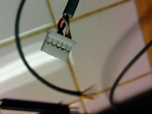
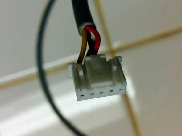
I got a Mitsubishi Heat Pump, which has pretty limited thermostat options, so I decided to build my own thermostat. There’s some basic connectivity info as well as a library that talks the protocol but I couldn’t find a ton of specific information on how to make the physical connection.
I used the following parts:
- JST PAP-05V-S housing
- JST SPHD-002T-P0.5 contacts
- Tensility 30-00394 4 stranded conductor 26AWG wire
- IWISS Crimping Tool
This crimp tool is definitely not the correct one for these contacts, but I managed to make it work. You should order at least twice as many contacts as you’re going to need because crimping is such a pain. (I started with 0 crimping skills. If you know what you’re doing then maybe it’ll all be easy.)
(Chris M reports success using simple crimp wires and soldering them instead of trying to crimp. He covered up the solder joints with heat shrink tubing. That’s probably a better method.)
Once you have the parts, they go together how you would expect. Crimp the contacts onto wires in the cable, then insert the crimped contacts into the housing. Because I did not want the 12V signal I just used a cable with 4 conductors. These conductors have to be stranded, otherwise crimping won’t work.
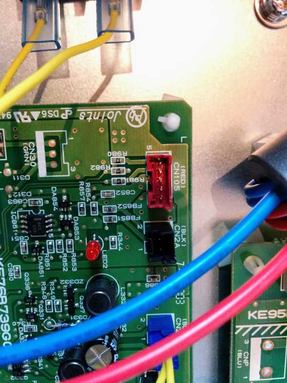
The picture above shows where to plug in the cable. It’s the red receptacle labeled CN105. My board nicely labels pins 1 and 5. (The marking for pin 1 is hidden in the picture, but you can clearly see the number 5.) The pin mapping is:
| Pin | Signal |
|---|---|
| 1 | 12V |
| 2 | GND |
| 3 | 5V |
| 4 | TX, data from heat pump |
| 5 | RX, data from thermostat |
Once it’s all done, the cable should snap cleanly into the receptacle, and come out when you press the tab.


